Post by Admin on May 21, 2016 12:14:32 GMT
I just received a mentee saying that he and his friends didnot understand what and how to connect several devices, diodes, transistors, resistors . LDRs motors etc.
In this LESSON, i will discuss and answer doubts individually to the best of my knowledge.
CONNTECTING LED TO PIN 13
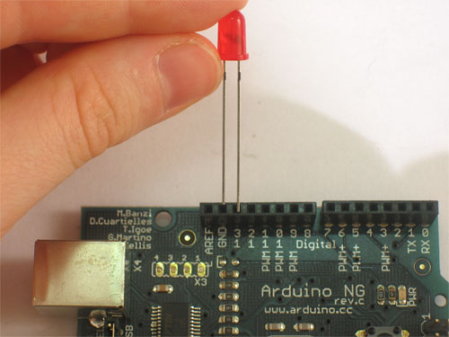
The 13 pin has an inbuilt LED and a resistor connected to it. So here theres no need to connect a external one. Simply take an LED, plug in the LONGEST pin to 13
Say hello to the resistor!
The resistor is the most basic and also most common electronic part. An electronic gadget, such as an mp3 player has easily a thousand resistors inside of it!

Thats a resistor
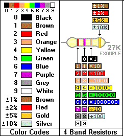
AS EVERYONE SHOULD BE REVISED FROM 11TH AND 12TH STANDARDs, where we learnt about the Resistors band?? BBROYGBVGW ?? YEA! THATS EXACTLY WHAT WE USE HERE TO FIND THINGS OUT.
Here is the thing, Refer here to find out how to measure resistance, At this point we are not focusing on the resistance. Just connect a 10 OHM or 100 OHM to the 0-12 PINs and work things out.
Say hello to the LED!
A diode is basically a one-way street for current. Imagine such a one-way street with a traffic policeman in front. If you want to turn onto the street the wrong way, he will not let you. Likewise the diode simply does not let current go through it the wrong way. Current in a diode can only flow from the positive side to the negative side.
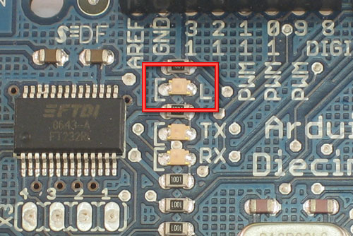
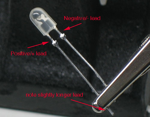
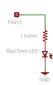
The picture shows how to connect a LED , 5V means -> THE GPIO PINS ( they give out 5V, as u should recall )
BREAD BOARDS
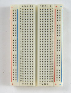
The connecting inside are quiet easy to understand, The red and blue lines? They are vertically connected. The middle ones are horizontal.
The entire bread board is separated into 4 INDEPENDENT Quarters. Check out yourself.
HEADING OVER TO SWITCHES
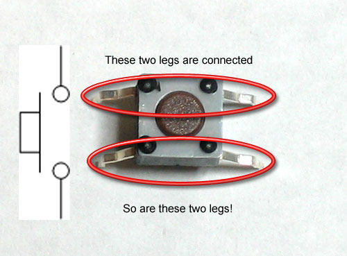
These mechanical devices have 4 legs, which may make you think that there are 4 wires that are switched on and off, but in fact, two on each side are actually connected together inside. So really, this switch is just a 2-wire switch.
The best way to completely destroy a microcontroller such as an Arduino is to feed it voltages that are much too high. Make sure your input voltages are between 0 and 5V! Never connect a 9V battery directly into an input pin, it will fry the pin for good and possibly destroy the Arduino microcontroller!
CONNECTING SWITCHES TO ARDUINO AS INPUTS
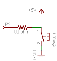
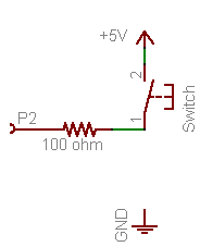
THE ABOVE diagram shows the pin connection of a switch working. SO why the external 100 OHMS?
There's a 100Ω resistor we use to connect the input pin to either HIGH or LOW voltage. Why is it there? Well, lets say you accidentally set P2 to be an OUTPUT type pin, but then you connected it to 5V. If you write a LOW to the pin (0V) but its connected to HIGH (5V), you've basically caused a short circuit at that pin. This isn't very good for the pin and could damage it! The 100Ω resistor acts as a buffer, to protect the pin from short circuits.
CHECK OUT HERE FOR THE BLUE PRINT FOR ARDUINO UNO
In this LESSON, i will discuss and answer doubts individually to the best of my knowledge.
CONNTECTING LED TO PIN 13

The 13 pin has an inbuilt LED and a resistor connected to it. So here theres no need to connect a external one. Simply take an LED, plug in the LONGEST pin to 13
Say hello to the resistor!
The resistor is the most basic and also most common electronic part. An electronic gadget, such as an mp3 player has easily a thousand resistors inside of it!

Thats a resistor
AS EVERYONE SHOULD BE REVISED FROM 11TH AND 12TH STANDARDs, where we learnt about the Resistors band?? BBROYGBVGW ?? YEA! THATS EXACTLY WHAT WE USE HERE TO FIND THINGS OUT.
Here is the thing, Refer here to find out how to measure resistance, At this point we are not focusing on the resistance. Just connect a 10 OHM or 100 OHM to the 0-12 PINs and work things out.

Say hello to the LED!
A diode is basically a one-way street for current. Imagine such a one-way street with a traffic policeman in front. If you want to turn onto the street the wrong way, he will not let you. Likewise the diode simply does not let current go through it the wrong way. Current in a diode can only flow from the positive side to the negative side.


The picture shows how to connect a LED , 5V means -> THE GPIO PINS ( they give out 5V, as u should recall )
BREAD BOARDS

The connecting inside are quiet easy to understand, The red and blue lines? They are vertically connected. The middle ones are horizontal.
The entire bread board is separated into 4 INDEPENDENT Quarters. Check out yourself.
HEADING OVER TO SWITCHES

These mechanical devices have 4 legs, which may make you think that there are 4 wires that are switched on and off, but in fact, two on each side are actually connected together inside. So really, this switch is just a 2-wire switch.
The best way to completely destroy a microcontroller such as an Arduino is to feed it voltages that are much too high. Make sure your input voltages are between 0 and 5V! Never connect a 9V battery directly into an input pin, it will fry the pin for good and possibly destroy the Arduino microcontroller!
CONNECTING SWITCHES TO ARDUINO AS INPUTS


THE ABOVE diagram shows the pin connection of a switch working. SO why the external 100 OHMS?
There's a 100Ω resistor we use to connect the input pin to either HIGH or LOW voltage. Why is it there? Well, lets say you accidentally set P2 to be an OUTPUT type pin, but then you connected it to 5V. If you write a LOW to the pin (0V) but its connected to HIGH (5V), you've basically caused a short circuit at that pin. This isn't very good for the pin and could damage it! The 100Ω resistor acts as a buffer, to protect the pin from short circuits.
CHECK OUT HERE FOR THE BLUE PRINT FOR ARDUINO UNO
